VHF Preamplifier for 50-70MHz
VHF Preamplifier for 50-70MHz
Biasing
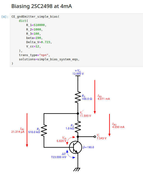
Using a 2SC2498, the datasheet suggests biasing around 4mA should give the lowest noise:
See Common Emitter Simple Bias with Grounded Emitter Calc for the python code I used to calculate this.
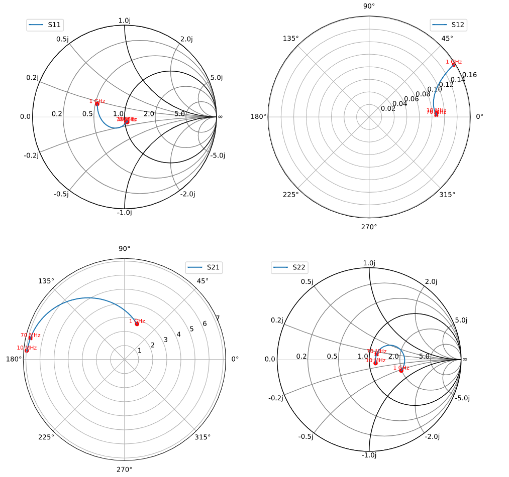
Modelling the Feedback Amplifier
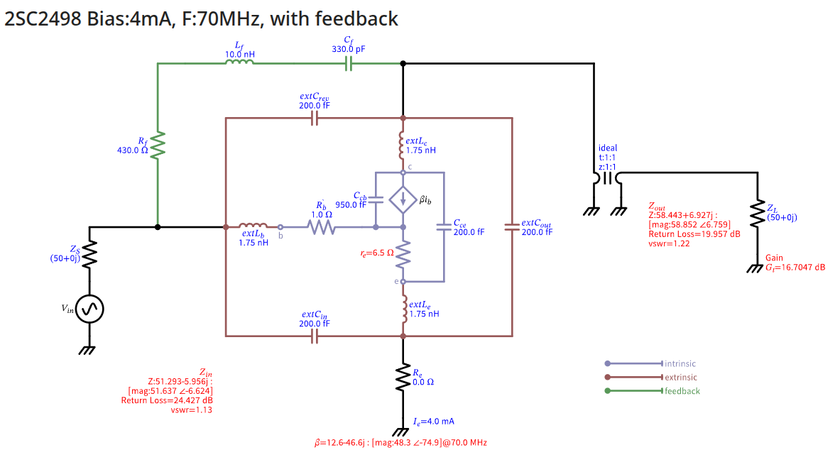
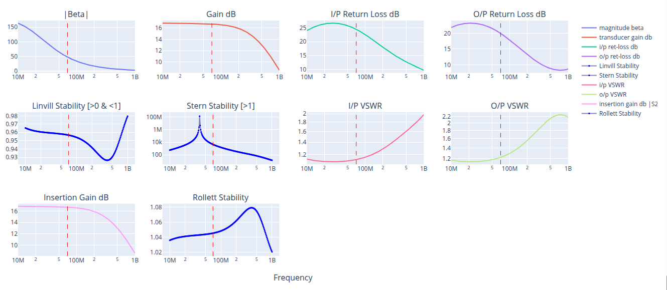
Using 2SC2498 Feedback RF Amplifier Calculator Study (in Python), focusing on 70MHz.
This models the transistor using the Hybrid-PI methodology plus addition of layers for intrinsic and extrinsic properties. Then adds the feedback network.
Note: If instability occurs below 10MHz then $C_f$ can be increased.
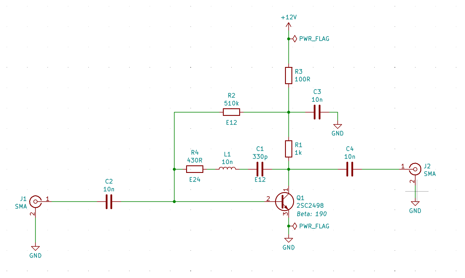
Schematic
Prototype
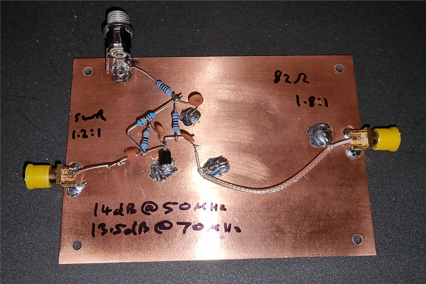
(Very)Ugly construction:
Notes:
- L1 represents the stray inductance of the feedback components’ lead lengths (10mm $\approx$ 10nH).
- Keep the transistor’s grounded emitter lead as short as possible.
Results
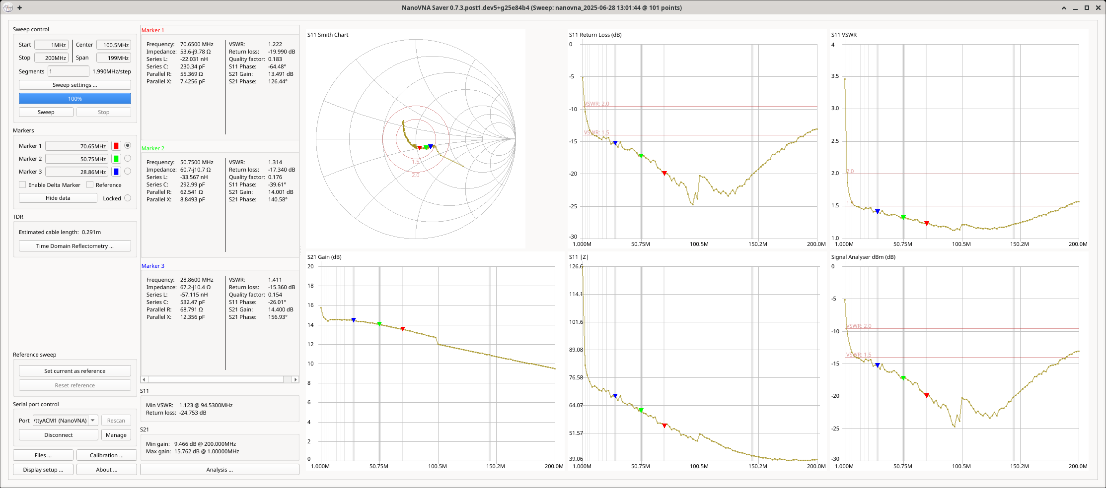
Although I was targetting 50-70MHz, it is pretty broadband.
Summary
| Frequency | i/p swr | o/p swr | gain |
|---|---|---|---|
| 7MHz | 1.5:1 | 1.3:1 | 14.3dB |
| 14MHz | 1.4:1 | 1.2:1 | 14.5dB |
| 28MHz | 1.4:1 | 1.4:1 | 14.4dB |
| 50MHz | 1.3:1 | 1.6:1 | 14.0dB |
| 70MHz | 1.2:1 | 1.8:1 | 13.5dB |
| 145MHz | 1.2:1 | 2.2:1 | 10.8dB |
NanoVNA Sweep
This post is licensed under CC BY 4.0 by the author.
